Showing posts with label tech talk. Show all posts

Mar 4, 2013

Tech Talk - Medical Device Particle Testing Part 3


Note: This is the final part of the medical devices particle testing tech talk, see part 1 and part 2.
Once the particulate test method has been validated, it is appropriate to start product testing.  The FDA guidance documents suggest testing finished devices subjected to sterilization, performing testing on the extremes and an appropriate intermediate size for the product matrix, and assessing both inter- and intra-lot variability.  A common way to meet these requirements is to perform testing on samples from design verification, aging, and three lots of process qualification.
The best practice would be to also test lots produced under worst case coating process conditions, which is the thickest allowable coating applied using the minimum cure time, although the FDA did not mention this.  If you do particulate testing as part of lot release testing, it is in your best interest to test the worst case coating process conditions.
It is desirable to finish as much testing as much as possible in one day; this makes the results more consistent and minimizes the amount of time spent cleaning.
A typical test format is:
  1. Perform test on water with glassware
  2. Perform test on water through the model without test device
  3.  Perform test on water through the model after test device is cycled
To test, first ensure the water and glassware to be used are acceptably clean.  For these examples it is assumed the validated particle method used 50 ml of water.  For example, if the test includes using a syringe to inject water into your model then collecting the effluent in a beaker, use the syringe to inject 50 ml of water into the sample collection beaker and test it.  The result should show a small number of particles in the 10+ um bin and very few (i.e. 0, 1 or 2 per ml) in the larger bins.  If necessary, clean your test glassware some more and then retest.
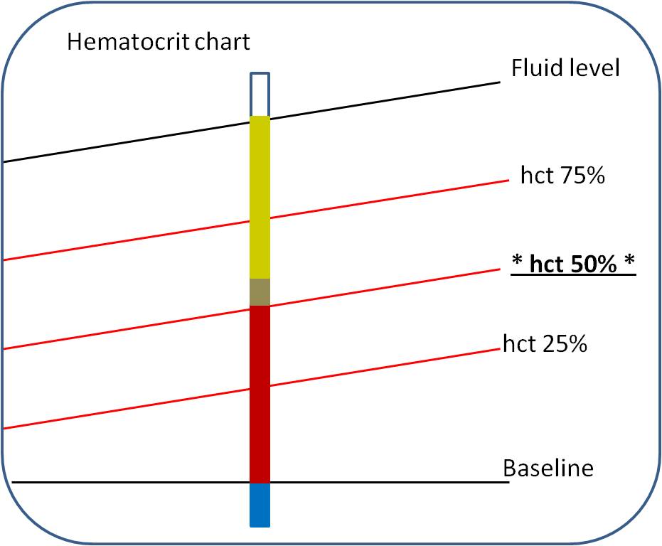
Next, get baseline results.  This can be done by injecting 50 ml of water through the model, collecting it in the test collection container, and then performing the particulate test.  This is the baseline and should be subtracted from your test device results.  Typically, the baseline has more particulates than the glassware test, but it should still not be that many.  If you see more than 5 large particles (i.e. 50+ um), I would rinse the model with water and perform the test again.  The baseline test may be performed before every sample test, per sample group, or per day.  Any of these methods is defensible.  You should also re-determine the baseline if a test condition changes, such as a new bottle of water is used. 
Then you’ll perform your test to typical use conditions. 
As before, a typical test might be:

a.       Fill model with 10 ml water, collect any effluent in sample container

This step ensures the model is hydrated prior to use, very few endovascular procedures are performed with a system that is not hydrated.  If the system is not hydrated the devices will likely generate extra particulates.

b.      Fill guide catheter with 1 ml water, collect any effluent in sample container

This step ensures the guide catheter interior is hydrated prior to use, for the same reasons as listed above.

c.       Perform simulated use with your device which takes 4 ml of water (obviously varies by device volume), leave device in model, collect any effluent in sample container

This step is the meat of the test.  Simulated use should match the IFU and typical use.  For example, if you have a guide wire and the IFU states to hydrate it for 30 seconds, you should hydrate it for 30 seconds prior to insertion into the RHV, through the catheter and into the model (the water used to hydrate is not used in the test).  Continuing the guide wire example, the guide wire should be advanced to a clinically relevant position in the model, and then retracted, the advance and retractions should be performed a clinically significant number of times.  For a PTCA catheter, the FDA guidance suggests inflating to the maximum labeled diameter.

d.      Flush guide catheter with 10 ml of water, remove device from model, collect any effluent in sample container

This is a typical example; the guide catheter is often flushed during endovascular procedures.  Using the guide wire example, you would flush through the guide catheter because it is standard practice and you will capture any particles removed from the outside of the guide wire.  Flushing through the guide catheter ensures you collect the most particles.  Alternatively you can perform a flush through the model with the guide wire in place, but the particles generated by the guide wire in the guide catheter will not be captured.  One could also perform both flushes to be conservative.

e.      Flush model with 25 ml of water, entirely empty model into sample collection container

Flushing after the device is removed from the model ensures that any particles generated during device removal are captured.

f.        Perform particulate count matching the validation conditions

Perform the test using the method previously validated.

g.       Flush the model with water

To ensure the model is clean for the next test, flush with water.  You can determine how much water is required by testing the effluent after a flushing, or you can perform a baseline test prior to every test as mentioned above.

h.      Identify particulate (as necessary)

Identifying the type of particulate can be done to determine the source of the particulates.  It is generally only attempted when an unexpected number of large particles are detected.  TIR42 lists typical methods for particulate matter determination.  To identify the particulate you have to retain the remainder of the sample, or collect it from the particle counter effluent.  Collecting the sample from the particle counter effluent can be challenging due to the particle counter volume.

To analyze your results, subtract the baseline the sample test results.  If the baseline had a higher result than the test (resulting it a negative number) it is generally acceptable to change that bin to zero, how to deal with this situation should be discussed in the protocol.  Finally it is generally desirable to convert the results to a per device basis and determine if the results met the specification.

Jan 2, 2013

Tech Talk – Medical Device Particles

Another area where the FDA has spent some of their focus is on particulates generated by medical devices.  A particulate is defined by USP 788 as “Particulate matter consists of mobile, randomly-sourced, extraneous substances, other than gas bubbles, that cannot be quantitated by chemical analysis due to the small amount of material that it represents and to its heterogeneous composition.”


The FDA guidance (PTCAballoons and stents) points out that particulate matter can be generated by the manufacturing process or from the breakdown of any coating (e.g., hydrophilic coating) on the device or from the device packaging. If particles are introduced in the bloodstream during use, they may present an embolic risk to the patient. Measurement of the total quantity and size of particulates a device may generate is an indication of embolic risk.

It used to be that medical devices didn’t have hydrophilic coatings and particulate really wasn’t an issue.  Then hydrophilic coatings came along and for a while USP 788 specification was adopted for use with medical devices.  If a small volume injection could have 6,000 or less particles 10 um (micrometers) or larger and 600 particles 25 um or larger, it seemed reasonable that if a medical device generated less than that it was okay.  A general note, particle counts are binned as 10+ um, 25+ um, etc.  The count for the 25+ um bin is included in the 10+ um bin, so the particle count will always decrease as the bin size increases, binning other ways may confuse people.

This worked for a while until people thought about it more and some of the coatings turned out to generate large numbers of particles.  The USP 788 specification has a significant issue, there is no discussion of upper limit of particle sizes, i.e. you could have a bunch of particles half an inch in diameter and still meet the adopted USP 788 specification.  The specification may work for injectables because you will not get half inch particles in a liquid and certainly can’t inject them anyway, but with a medical device you just might be able to.   Since that question has come up, AAMI TIR42:2010 was released with a section on the clinical significance of particulate matter which basically concludes that particulates less than 100 um are not a major concern.  There is less evidence showing any particles larger than 100 um are safe (although they may be).  This just further highlights the inadequacy of using USP 788 as a particulate specification for medical devices.

So while you may still use an adoption of USP 788 as your specification, you do so at your own risk and you’ll probably need some further explanation for the FDA.  What specification you do choose is tricky though, as you probably do not want to set a specification of zero particles 100 um or larger.  First, is this clinically significant?  Second, in my experience every now and then you will get a particle that large, it may not even be from your device, but it will show up in your environment results.  If you have a history of using USP 788 for other devices on the market, you can probably use that if you’re comfortable with it, along with a clinical evaluation of your results on the larger particles.  However, the FDA has left the door open here for you to accept larger numbers of particles than USP 788, which for some coatings may be required, the AAMI TIR42 standard references plenty of literature saying large numbers of small particles are unlikely to do harm.  Alternatively, you could compare your results to results from a similar device on the market, but this method is riskier, expensive, and is going to be less repeatable.

Part 2 of this series discusses the test method and how to validate it.  Also see Part 3, Medical Device Particle Testing.

Jun 16, 2012

Tech Talk – Medical Device Colorants

In the last few years the US FDA has been asking more questions about color additives (colorants) in medical devices.  A colorant is what makes your medical devices a pretty color, and may be composed of several pigments.  This is not so much a secret to endovascular companies at this point, but if you have any colorant in your device you will get questions from the FDA unless you address them beforehand.  It is important to note, device biocompatibility testing will not save you, you will not be able to hide behind it, and you will have to do more.  Unless you want a delay in your submission processing, I suggest you include them with your initial submission.  Not so much EU or Japan, but you may still get a question now and then. The FDA has issued guidance, but it is not really specific.


What are the questions from the FDA?
  1. What are the colorants?  Identify by chemical name and CAS #.
  2. What are the colorant weight percent (wt%) in each component and total colorant weight per device?
  3. Submit colorant MSDS.  (Hopefully it matches the answers to item 1…)
  4. Are the colorants are on 21CFR 73, 74, or 81?
  5. Have the colorants been used in any US approved predicate devices?
  6. If no to 4 or 5 they probably want to see a toxicological risk assessment.
Recently the FDA has stopped asking for color additive petition for the colorant used if not on the FDA lists, so you probably don’t have to worry about that.  (If you do get that comment you should probably push back because it can take years to get on that list.)

I would stick all this information in the biocompatibility protocol / report you submit them with the materials list and hopefully that would head off any comments and delays in your submission.  Alternatively you might create a separate report since other regulatory bodies don’t always ask and it may raise questions- don’t forget to submit the separate report to the FDA.

For items 1 through 4, you should be able to address those with a little help from your suppliers and a web search for your colorants on 21CFR73, 21CFR74, and 21CFR81.

You should create a table similar to this example:
Complete for all components and then list the total amount of each colorant in the device.  You may split up components by contact type (i.e. blood contacting or not).

If your colorants are listed on the approved colorant lists you don’t really need to worry so much about item 5, but I would complete it for thoroughness.  If not… hopefully your company has used the colorant before, or you’re in for a bunch of meetings trying to figure it out.  Maybe if you had someone else design the device they have used the colorant in other devices and well tell you, but otherwise it is probably impossible to figure this out.  At this point, you want to find anything that has used the colorant, even if it is not the same use as your device.

If you have to go the toxicological risk assessment route (follow ISO 10993-17, Biological evaluation of medical devices – Part 17:Establishment of allowable limits for leachable substances), MDDI has an article on the details.  Also ISO 10993-7 has an example of a toxicological risk assessment for ethylene glycol (EG) (take that Japan!).

I would just pay someone to do it, depending on your approach; you will be out about $20,000+ (with about half testing and the other half the risk assessment) and a couple months.  The analysis usually involves using exaggerated extraction of your device in multiple solvents (saline, ethanol, hexane, etc.), using various chemistry techniques (GC-MS, HPLC, etc.)  to analyze the extract, and then performing a risk analysis on the chemicals found.  If that doesn't work out well, then repeat with leachables and write justifications.  For example, justify why hexane extracts aren't relevant to the clinical use of your device.

NAMSA has a seminar this type of toxicological risk assessment, but your company probably lacks the tools to perform the risk assessment as you may need access to various toxicology databases.  If your company does not have the expertise, most likely they will assign one person to do it, that one person will do it, then have to convince 3 or 4 other departments (regulatory, quality, clinical, etc.) that they did it right and teach them the method.  Whereas if you hire the so called expert, most people accept the results, slap a cover page on it, and ship (unless they disagree with the results…).  NAMSA, Toxikon, WuXi AppTec, and some chemistry labs will all do this for you.

For future medical device designs, I would stick to natural color or colors on 21CFR 73, 74, or 81, which really covers all of your standard colors.  Certainly don’t take whatever your extruder has on hand.  Although another blue catheter is not exciting, you’ll get to market quicker.  These are medical devices, not electronic gadgets for 14 year old girls- your customers won't care.

Oct 27, 2011

Tech Talk – In Vitro Medical Device Verification Testing in Blood

I previously discussed testing medical devices in blood here (in 2007!), but I think I did a poor job of it and I’d like to revisit it.

Why do you test in blood? Well for one, blood is hard to simulate, it’s a non-Newtonian fluid, and using glycerin and water don’t really do it justice, but these can work depending on the application. For another, a common blood test is to check for hemolysis, sure this is tested during a biocompatibility test, but biocompatibility tests are not performed during actual use conditions. Hemolysis may also be a part of an animal safety study that you want to check out beforehand.

Where do you get the blood from? At a slaughterhouse of course, if you can find a smaller or craft meat location in your area, they’ll probably work with you, one used to sell to us for $40 a week, and we’d take a couple gallon buckets and their workers would fill them up while we waited. They only slaughtered on certain days, so call ahead. You’ll probably find cows easier to find and work with, but there isn’t really a reason you couldn’t use pig blood.

Before we leave for the slaughterhouse we’ll set up a water bath at 37ÂșC to be ready when we get back. Then we’ll add anticoagulant to the blood collection bucket. We’ll use either heparin or Acid Citrate Dextrose (ACD).

Once we get the blood, we mix the bucket to ensure the anticoagulant is distributed in the blood. Heparin is prescription drug, so hit up your vet consultant or animal lab for some ahead of time. ACD you can make based on USP guidelines from commonly available chemicals (water, citric acid, dextrose, and sodium). We used around 10,000 to 20,000 units of heparin per liter of blood. Of note is heparin is used clinically (on people) more in the U.S. and ACS is used in Europe, so you could maybe argue for the use of one over the other, but you’re using animal blood, so I’m not sure if that really matters. I’ll assume we are using bovine blood for the rest of this post. If you don’t use an anticoagulant, you’ll end up with a clot bucket when you get back to the lab, just throw it away if this happens, it is not recoverable.

Time is generally of the essence so don’t stop by Chili’s on your way back to the lab. Also, just be aware that water will damage your blood cells, so it is preferable to rinse your lab ware with a bit of saline before use.

When we get back to the lab we first check the blood pH and temperature, ideally the pH is between 7.2 and 7.4. We then take a hematocrit (hct) measurement by collecting blood in a capillary tube with clay sealant to stopper the bottom (get blood before using clay). Then we centrifuge the capillary tube for a few minutes at high rpm. Once centrifuged, the capillary tube will look like this:


You’ll need a hematocrit chart. Below is a simple representation of how to measure hematocrit, you put the capillary tube on the chart, line up the clay on the baseline, you move the tube left or right until the fluid level matches the top line, then you find the line where the red blood cells stop and follow it over to read the percent hematocrit, in this case 50%.


We generally take two hematocrit measurements and average; you need two capillary tubes to balance the centrifuge anyway. 38 to 42% hct is a typical range for a study like this one, although it will vary depending on how much the animal drank before it was slaughtered, I’ve seen it come in in the low 20s, so don’t worry about the initial hematocrit too much.

We then pump the blood from the collection bucket through a saline primed arterial filter (pediatric filters have lower priming volumes) and line to remove hair and large clots and into a carboy with a plugged outlet at the bottom. We’ll set up a circuit from the bottom of the carboy to the top (through the filter) with a peristaltic pump to keep the blood circulating. Place the outlet in the blood and not above it or you’ll get a bunch of foam. At this point we’ll add saline to the blood to get the hematocrit where we want it, usually around 22% to 32%. Keeping hematocrit consistent is better than not. We’ll measure the hematocrit and adjust until we’re good, using the following formula:

 S = [(H/F)-1]xV
 Where:

 H is the initial hct,
 F is the desired hct,
 V is the original volume of blood, and
 S is the volume of saline to be added.

Once we get the hct where we want, we’ll measure pH and temperature again. At one point we were centrifuging the entire sample to remove the buffy coat layer between the serum and the cells, then mixing it back together but this proved pointless and didn’t really benefit our results or affect our testing any and it was a major pain, so I don’t recommend it.

Once prepared, we can expect the blood to last for five or so hours before it gets questionable. If we’re testing an endovascular device, we’ll pump the blood around a tubing circuit (using a peristaltic pump) and then place the device in the tubing. Preferably the tubing is a similar inner diameter to the artery or vein the device will be used in. You probably want to place the blood reservoir above the test set up and the pump after the test area. Putting the blood reservoir above the test set up ensures a more consistent blood flow. A simple set up is shown below.


We can measure the device performance in blood directly, or we may be interested in something like how much does the device damage the blood, we’ll check the serum and see how red it is in simple terms. If it gets worse over time, then we’re damaging the blood. In this case, for an accurate comparison we need to run a control at the same time. For example, if we have an elaborate pumping system, we’ll run our pump system on one closed circuit and the control (with no device) in another closed circuit and track the hemolysis of both over time.

Oct 16, 2011

Tech Talk – Stroke Treatment with Medical Devices

I thought I’d move into a newer area for medical devices, stroke treatment.  Stroke affects more than 700,000 people a year in the US alone, of these, over 150,000 die.  Most of the strokes are ischemic in nature.  Unfortunately the treatment options are very limited and time to treatment is absolutely critical to a good outcome.  Successful recanalization of the occluded cerebral vessel during the acute ischemic event is associated with lower three month mortality and improved functional outcome.  [Source]

Intravenous Tissue Plasminogen Activator (tPA) is the FDA approved drug for acute ischemic stroke for up to three hours after the stroke.  This drug can dissolve the clot and is sometimes applied right at the clot through a catheter.  This is generally the first form of treatment; however, tPA is not effective in all cases and can cause bleeding in the brain, particularly in older patients. 

Mechanical removal of the clot using a medical device is being performed more and more alone or in conjunction with tPA.  These devices have some advanatges over tPA, including more rapid achievement, ability to treat large vessels, and lower risk of hemorrhagic events.  Only two neurothrombectomy devices are currently cleared for use in the US.  You don’t have to be a rocket science to figure this one out- 700,000 people affected and two cleared devices, stroke treatment is a screaming opportunity for medical devices.

The FDA defines these devices as neurothrombectomy devices, these are devices intended to retrieve or destroy blood clots in the cerebral neurovasculature by mechanical, laser, ultrasound technologies, or combination of technologies.  The FDA has provided guidance on these devices, one note of interest is that a clinical trial must be performed due to the high risk of the device.

There are some general procedural steps common to both devices that I will cover quickly now.  Both devices must have access to the clot itself.  This means advancing a guide wire and catheter using angiography to the clot first. Don’t tell cardiologists, but this is more difficult in the head than in the heart- there are many more possible pathways and the vessels are generally smaller and more easily damaged.  If the patient has been given tPA any damage can be catastrophic.  Angiography is also used to measure the vessel diameter so the appropriate sized device can be chosen.

Another procedure common to both devices in certain situations is the use of a balloon guide catheter with aspiration.  The balloon guide catheter is inflated, which blocks blood flow in the blood vessel with the clot.  Aspiration is then applied, this means taking a large syringe (typically 60 ml) and pulling it back, sucking whatever you can out of the blood vessel, alternatively you can buy a pump to do this.  Minimizing balloon inflation time is important because the lack of blood flow is what causes a stroke, you don’t want to compound the problem.

The two approved devices are shown below:
                                            Merci Retreiver (left) and Penumbra System (right) Image source.


The first FDA approved neurothrombectomy device was the Merci Retriever by Concentric Medical.  The device was approved through the FDA 510(k) process in 2004, the current indication for use is:
Merci Retrievers are intended to restore blood flow in the neurovasculature by removing thrombus in patients experiencing ischemic stroke. Patients who are ineligible for intravenous tissue plasminogen activator (IV t-PA) or who fail IV t-PA therapy are candidates for treatment. Merci Retrievers are also indicated for use in the retrieval of foreign bodies misplaced during interventional radiological procedures in the neuro, peripheral and coronary vasculature.
The Merci Retriever system includes a flexible nitinol wire coil formed into what looks like a corkscrew.  The latest version of the device has filaments (made of suture material – I would guess nylon) that provide an additional mechanism for securing the clot during removal.

Basically, the device is advanced distal to the clot, deployed, turned, and when pulled back through the clot it captures the clot in the corkscrew and the device is then removed from the artery while under balloon aspiration.  The balloon aspiration (pulling a vacuum on the vessel while a balloon blocks it) minimizes pieces breaking off from the clot and causing additional issues.  [source]  You can watch a demonstration of the device here

Concentric Medical was recently bought by Stryker for $135million, which goes along with Stryker's previous purchase of Boston Scientific’s neurovascular division.  I don’t know what Concentric’s revenue was, but I think this sounds like a good acquisition, with the caveat that the Concentric team must remain focused on Stroke treatment and not get caught up in all the other things Stryker does.

The second device in use is the Penumbra System of Continuous Aspiration Thrombectomy by Penumbra. The Penumbra System is used for the “revascularization of patients with acute ischemic stroke secondary to intracranial large vessel occlusive disease…within 8 hours of symptom onset”.  The device is first advanced to the blood clot, the Penumbra Catheter’s tip is then placed at the proximal end of the clot.  The Penumbra “separator” is advanced to the clot, aspiration is started, then the separator is used to help to break up the clot (or “debulking”) and make it easier to suck into the guide catheter.  The separator has a straight tip and a cone (purple cone shown in the picture).  In theory, there should be less damage to the vessel with this system, this is important if the patient has received tPA and that has not worked. 

As reported in a State of the Evidence article, the clinical effectiveness of the devices, defined as the having a good outcome (modified Rankin Scale score 0 to 2), rates ranged from 21 to 36% with the MERCI and 20 to 48% with the Penumbra System.  These numbers are not necessarily comparable to each other as the devices can be used for different types of clot.  Presumably the Merci retriever is typically used for “hard” clots and the Penumbra system is used for softer clots (This is just my guess).

Other types of devices sometimes used off-label in the US, such as snares, exist, but I would expect their use will decline as more devices get approval for stroke treatment.  Additionally, stent retrievers are available in the EU, but not yet approved for the US, I assume these devices will be approved in the next year or so and if you were so inclined you could roadmap out which ones are doing well in the EU and make an investment on that.  The EU is currently two or so years ahead in types of devices available for stroke treatment.  Other devices are certainly under development, with ideas from coronary or peripheral vascular being expanded for use.  Startups include Insera Therapeutics who is developing a snare type device.   I wasn’t able to identify any more in a few minutes of Google searching- if you know of any, leave a comment and I’ll add them later.

Update:  In 2012 two more stroke treatment devices were approved by the FDA, thee Solitaire FR by Covidien and the Trevo by Stryker.  Clinical trials for both of these devices showed that they were superior to the Merci Retriever.  

Aug 29, 2011

Tech Talk – Anatomy Models and Medical Device Testing

One important consideration to take into account while designing and testing medical devices is how they’re going to be used. In the case of vascular devices, they will be used in arteries and veins and I’ll describe some of the test considerations. While performing your verification testing, you want to ensure that you have a reasonable clinical model to perform testing under.

For example you might have a device that is intended to be used in the Right Coronary Artery (RCA) as shown below (image from Wikipedia):


How do you ensure your device works correctly without using it on a person? You find an appropriate model.

Models of various anatomies are available from Elastrat and Shelley Medical Imaging Technologies. ASTM F2394 also contains a schematic of a two dimensional (2D) model recommended by the FDA for some applications. Although it is best to ensure you pick a model based on the vessel characteristics that your device will likely see (such as vessel diameter and tortuosity). Using the ASTM or another off the shelf model can get you into trouble if for example you’re testing a guide catheter and pushing it into the smallest vessels when it is only intended to sit in the aortic arch.

A 2D model is easy to construct and use, but not necessarily the most accurate, it generally consists of just two pieces of machined plastic (bottom with a clear top) with a piece of tubing inserted. The easiest model consists of just a radius as shown below (by the way, I did the diagram myself in MS PowerPoint!).


Ask your clinical source what the tightest radius your device is likely to see in-vivo and simply machine a curve of that diameter. Insert a piece of silicone tubing into that radius to simulate a vessel wall more accurately than hard plastic and you’re ready to get started (you can use pig vessels to line your tortuous pathway, but this is no fun to set up). It is easy to create 2D models of various tortuous pathways. Creganna (Medical Device Technology, May 2006) shows an example tortuous pathway in some of their coronary block model simulated use testing:


You can see the simulated aortic arch as the large looping arch (start from the top most pathway) and then into tighter arteries as the model continues.

A 2D model obviously lacks some realism as it is possible that your device will need to turn multiple planes during use. Although it may be argued that the worst case scenario is actually the 2D model as it stresses only those two dimensions, adding the third dimensions allows additional flexibility in most devices as they are generally concentric. In the case of a non-concentric model, you can perform your testing to the worst case in the 2D model, setting your weakest side up to take the most abuse. The 2D model is also arguably tougher on your device than clinical use as the give is limited to the wall thickness of the tubing you insert.

For 3D models, you’re probably better off buying one from the companies listed above, although they can get expensive, and can be damaged so you need to be careful. An example heart model from Elastrat is shown below.
Once you have your anatomy model, you generally want to further simulate clinical conditions, either by flowing 37C saline through the model, or a mixture of glycerin and water to simulate blood flow.

Now you want to run whatever tests you can using the model. For example, a guide wire or catheter turns to failure test is simple enough, just hold the distal end and turn the proximal end until the device breaks. However, to really simulate use, you should put the device through the model, and while the device is still in the model, hold the distal end then turn the device until it breaks. The addition of the model adds a bit of complexity to the test, but is a better test system.

I have seen the FDA question models, so document your clinical justification why the model you use is appropriate in the protocol. If you’re using a model that you bought, you should ask them to provide you with the justification.

Aug 1, 2011

Tech Talk – Catheter Bonding

Tech Talk – Medical Device Catheter Bonding

For my second tech talk I thought I’d briefly cover catheter bonding. The typical vascular catheter is made of several types of polymer; it is of obvious importance to connect them in a precise way. A typical bond will consist of two types of tubing; a popular choice is Arkema’s Pebax. Pebax is a USP class VI material that stands up well to sterilization and takes colorants well; it is widely used in current catheters. Bonding will consist of something like 72 durometer on the proximal end of a catheter to 63 durometer on the next step, then moving down the catheter until you reach 35 durometer at the tip. Ideally, the two pieces of tubing are the same size, but they can be of slightly different inner and outer diameters. Starting with your two pieces of Pebax tubing:

Since Pebax isn’t as smooth as most physicians desire, a PTFE or HDPE liner is usually used on the inside of the catheter. The liner allows for smooth delivery of other devices such as guide wires or other catheters down the catheter. A liner will not be required for something like an inflation lumen. Liners may also be multiple layers to better bond with the Pebax. A mandrel is placed inside the liner or lumen. The mandrel is usually coated with PTFE (by companies like Applied Plastics) or parylene for easy removal later on in the process.

Fluorinated ethylene propylene (FEP) tubing is then placed over the Tubing joint. FEP is available off the shelf in multiple diameters and wall thicknesses, it can also be custom made if required by companies such as Zues and Fluortek. Using FEP forms a more consistent and even joint.

Apply heat to the FEP tubing to shrink it and melt the Pebax. Pebax melts at around 174°C so usually 190°C is enough heat. To heat, Beahm Designs makes off the shelf heaters that apply a constant stream of air at a set temperature. Alternatively heat guns can be used, although long term you should look for a more controllable solution.
After heat is applied and the part is allowed to cool, cut off the FEP tubing with a razor blade (slice more parallel to the tubing, not straight into the middle of the FEP) and remove the mandrel and you have a very nice piece of tubing that is very difficult to tell where the transition is.
For a catheter you may actually have five or six transitions such as this depending on the stiffness you want and the number of lumens you want at each point. It is also possible, but not as desirable to join two types of tubing using adhesive, this may be required if the polymers are too different to heat bond. In this case, one piece of tubing fits into the other.
The adhesive used for medical devices is generally made by Dymax or Loctite and can be UV or heat/time cured. UV cure is superior for manufacturability as you can quickly pass it to the next operation, but it may not be possible to use UV adhesives in all cases.  The geometry of this catheter is more difficult and the liner may have to be tapered.
Advanced Polymers also sells a polyester heat shrink tubing that can be left on the device and used in catheter bonding if these two methods don’t quite work for you.

After bonding you will want to validate your design and process using methods such as tensile test to ISO 10555 and burst pressure to ensure it is high quality. Catheter bonding is something that has been fairly extensively developed and you can get lots of support from suppliers, but it always turns out you need to know one extra trick that you have to develop yourself.

References for this post are The Medical Device R&D Handbook by Theodore R. Kucklick, Beahm Designs, Arkema, and personal experience.

Jul 12, 2011

Tech Talk – Guide Wires


I sometimes enjoy The Oil Drum’s tech talks, so I thought I’d give one a try.
Guide wires, or guidewires, are used in the vasculature to act as a guide for other devices, an example video shows guide wire and stent.  Guide wires are generally more flexible and steerable than devices used to treat or diagnose patients.  Typically, once access to an artery is gained, the guide wire is inserted and steered under fluoroscopy to the location of interest.  Then one or more devices (usually catheters) are delivered over the guide wire to diagnose and treat the condition.
Guide wires usually come in diameters of 0.010” to 0.035” with 0.014” being the most common (0.013” is equivalent to one french or 1/3 of a mm – so the typical guide wire is slightly over 1 french in size).  Guide wire lengths vary up to 400 cm, depending on the anatomy you want to reach and the work flow.  The flexible distal tip portion is usually 3 cm long, the slightly less flexible portion is usually 30 to 50 cm long, the less flexible proximal portion makes up the balance.

The user requirements of a guide wire are can it quickly get to where it needs to go and then can I reliably deliver devices over it without patient safety issues.

A typical guide wire construction is shown below:


In this diagram, the blue proximal section is the hypotube, similar to a syringe needle (minus the sharp end).  The hypotube is generally coated in PTFE- but other coatings are also used.  The PTFE coating allows devices to more easily slide over the guide wire and is probably the major component in device “deliverability” on the guide wire side.  It is easier to slide a catheter over a guide wire with PTFE than it is to slide a catheter over a guide wire without PTFE.  The PTFE coating of the hypotube can be a tricky part of manufacturer and is usually outsourced.  Just as your pans vary in quality of the non stick surface, so do guide wires and different variations in processing and materials can affect how well your guide wire delivers devices.

The core wire material is usually nitinol or stainless steel and tapers from the proximal end to the tip.  At the tip it is generally flattened.  The core wire affects the torquability of the device; you want the tip of your guide wire to turn in a 1:1 ratio with the proximal end.  The torquability affects the steerability of the device, can it get to where you want to go.  Nitinol core wires are harder to kink, but can lose some torquability.  The core wire is attached to the proximal end of the hypotube using solder or adhesive.

Alternative guide wire construction can look like this:

In this design there is no hypotube, the core wire is the proximal portion of the device.  Coating is applied directly to the core wire and you have better torquability because you are turning the core wire directly, instead of turning the hypotube, which turns the core wire.
In both designs, the next section is a more flexible distal section, usually consisting of a wire coil.  The connection is made to the hypotube or core wire by solder or adhesive at this point.  The coils are more flexible than the hypotube and the distal portion of the device is suited to navigate to the desired portion of the anatomy.  There may be several types of coils attached together or one long coil where the coil spacing changes.  The more proximal section of the coil is generally made of stainless steel for cost savings.  The distal tip coil of the guide wire is made of radioopaque metal, generally a platinum alloy, but a palladium alloy may also be used.  Some hospitals recycle these religiously for the $4 in platinum they can get in the tips.
At the very distal tip, the wire coil is soldered to the core wire using tin - silver solder, although in some older wires the core wire may be attached using adhesive.
The tip itself is rounded into a ball shape, which the solder or adhesive naturally forms when applied to the tip.  This allows the guide wire to follow the curve of the vessel and is generally called an atraumatic tip.  From a manufacturing point of view, manufacturers are very careful to not allow any burrs in the tip assembly for fear of vessel damage, but I have not seen any direct reports of vessel damage caused by badly made tips.
The tip itself is always shaped by the user to aid in steerability, usually to around 45 degrees.  Usually the tip is shaped by using an introducer or needle.  Here is a video of a shaped tip, although this method isn’t encouraged.  Some manufacturers offer tips pre-shaped.  One notable alternative tip construction is shown below:


In this case an extra wire has been attached to the core wire and the tip to allow better tip shapeability and can give a softer tip.  Depending on where you want to go in the vasculature different tip softness is desired, for example in the cerebral vasculature usually the softer the better.  Tip softness can be measured as tip load, the amount of force (or load) it requires to bend the tip a certain amount.  Obviously you want the tip to flex instead of damage the vessel wall.
The distal portion of the wire is coated with a lubricious coating, generally a hydrophilic coating, older wires used hydrophobic coatings, but they are becoming rarer.  The hydrophilic coating is a proprietary coating that manufacturers generally outsource and pay a considerable amount of money for.  There is some skill in developing a coating that does not come off of the guide wire, and retains its lubricity over time.
When building a guide wire you want to start at one end and work your way down, starting at the tip and working to the proximal end.  Making guide wires is not that labor intensive with the most skill you need is to be decent at solder and soldering cleaning.  You need to work at keeping them undamaged in manufacturing due to their small size and the less flexing of the wire you do the better.
There are other variations on guide wires, such as plastic coatings and different combinations of coils and hypotubes, but I’ve covered the major ones.  Guide wires are basically a commodity at this point and only the regulatory barriers to entry and the fact that physicians aren’t typically price sensitive are keeping it as a reasonably attractive market to pursue.
When performing performance verification testing on a guide wire, some common tests are turns to failure (you clamp the distal tip and turn the device until it breaks), particulate / adhesion tests (of the coating), tip tensile strength, torquability (which you turn the proximal end of the guide wire a set amount and measure how much the distal end turns), tip load, radioopacity, and deliverability (where you measure the force it takes to move a catheter along the guide wire).  DDL has uploaded this video on testing a guide wire to ISO 11070, but I’ve never used that particular test.
For validation testing you generally request feedback on navigating a guide wire to the desired location in a bench or animal model and delivering a device over the guide wire.
I was unable to find the size of the guide wire market, but every endovasculature procedure uses at least one guide wire, many times more.  Many companies outsource the manufacture of guide wire to a contract manufacturer; it is difficult to enter the market fresh at this point.  However, as a company, you want to sell a guide wire so you can get your 40% margin on an outsourced guide wire instead of the competitor getting 60%.  Also, it is generally beneficial to sell a whole suite of devices when selling to a hospital, if you sell only catheters you will have a harder time getting shelf space unless you can bundle it with other products.

More information is available at:  PCI equipment: Guidewire selection.  And the FDA chimes in with helpful guide wire tips on device safety-  always read those IFUs.